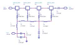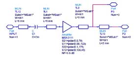

The second amplification stage, in the direct conversion receiver, was designed by ourself.
Our goal was to obtain a gain of more than 50dB with a reasonable resistance to intermodulating signals ( strong GPS signals, higer frequency UHF band TV signal etc. ).
Since that we had some MSA2111 Agilent MMIC samples, that are cheap, quite easily cascadable, with good gain and IP3, we designed a four stage postamplifier using that components.
The RF design :
 |
 |
| Four stage 1420 MHz postamplifier | Single stage design |
The PCB is a conventional double side FR4 board with a thikness of 1.6mm. GND areas on TOP of the board are connected to bottom GND plane via holes and copper wires soldered.
The microstrip lines used to interconnect MMICs of different stages has a width W1=2.5mm and lengths indicated in the schematic: it realize a good impedance matching with 60um copper thickness PCB.
50 ohm SMD resistor are connected between 5V DC supply and the output of each stage, between a 3.3uH RF choke, just to set a bias current of 28mA to each device.
Performances are interesting: NF= 3.9 dB and overall gain of 50dB, with the board into a home made sheet-brass enclosure with SMA connectors and a 1000pF bypass capacitor for DC power supply input.
Due to high gain the RF design should be particularly cured to avoid self oscillations of the amplifier. After first measurements, we found that a 100nF capacitor, placed in a precise point along the DC supply chain of the four MMIC, was very useful to turn off any oscillation, also if gain was little bit reduced by the impedance matching degradation between two faced stages. Look carefully to the position of that capacitor in the amplifier photo.
On the same board, there is also the KF50BD 5V DC regulator in SO8 SMD package: it has a wide DC input voltages but we suggest to stay within 7-10 volt range to avoid excessive heating of the regulator itself.
You can see complete layout on following pictures:
PDF file 1:1 scale of the PCB: 4xMSA.pdf
We are currently preparing new version of this amplifier with only two MSA2111 stages. It should be less critical for stability and more flexible to use.
New layout will come soon....
